
We set out to add an SD-Card logger to our existing ZED-F9P rover module in order to gain additional stability in logging our GNSS observation and navigation files generated by the rover. If you are just starting out in setting up an F9P base or rover module, definitely check out our original post and video here.
Update: Please see the Materials List at the bottom of this post for a complete list of items needed to complete this project.
Here is our original wiring diagram, including a Bluetooth module to send data (RTCM corrections from base) and receive data (observation/navigation data for PPK) from the rover F9P module:
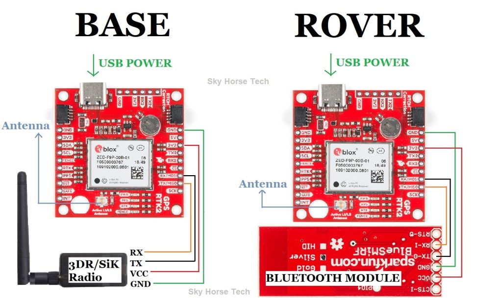
One of the weak links in this setup is the bluetooth module’s ‘send/receive’ functionality between the rover F9P and the smart device app which logs data. As we all know, any bluetooth connection can have intermittent drops which means your end-product, the GNSS oberservation and navigation files, being logged on your smart device will also have missing data. This will become evident when processing in RTKLIB as you may have several periods of red-line errors in the PPK plot. Not good.
In order to shore-up this weak link we can use an SD-card logger that is hard-wired directly to the rover F9P. There are standard SD-card loggers out there which work fine, reading in data from one of the UART ports and writing that incoming data directly to the SD-card. A more elegant approach is to use an SD-card logger that is attached to a micro-computer (Arduino, Raspberry Pi) to perform some of the processing on-the-fly, generate checksum calculations for data verification as well as creating new files after a given amount of time (every 15, 30, 60 minutes).
One of the best Arduino SD-card loggers on the market is the Adafruit Feather M0 Adalogger. This lightweight phenom has plenty of processing power with 32K of RAM at 48MHz. The chip used here is the same one found in the Arduino Zero.

There are plenty of Arduino sketches out there which are designed around logging data to an SD-card. One of the best that we found was by Paul Clark and his RAWX logger designed around the Feather M0 board. His GitHub page around this RAWX logger details the wiring diagram along with the Arduino sketches for serial port and I2C versions. Here is what Paul’s version looks like, with the Feather M0 connected to the ZED-F9P:
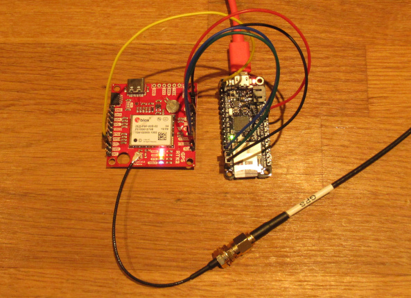
This works great on its own and can be a solution many people find helpful. For our needs, we needed a bit more functionality such as an LCD screen to show the current status of the logger and an integrated bluetooth module for incoming corrections data. Paul’s version prints out status reports to the Serial port, for this scenario the user just needs to be connected to a laptop to view that data over the Serial monitor.
For our forked version (https://github.com/SkyHorseTech/F9P_RAWX_Logger) we add the LCD screen functionality, bluetooth connections to UART2 for automatic processing of incoming RTCM data from base F9P (through Lefebure NTRIP client), and also revised the ‘Stop Logging’ button logic. The Stop Logging button in PaulZC’s code will close out the file and wait for the user to push the reset button on the Feather M0 before doing anything else.
As an alternative, our version found on GitHub in Arduino/RAWX_Logger_F9P_I2C_LCD is more of a ‘Reset Logging’ button in that it will close out the current log file and open a new file, logging to that, chugging along not waiting for any additional input from the user. One item of note with the Feather M0 is that if it is logging data and you unplug the power to it, it will lose all of the data in the current file. This makes closing out the file very important, in order to preserve that data that has already been logged. If the reset button is not pressed, the Arduino sketch will use the hardcoded interval length to close out files and open new files automatically after the interval time has elapsed. To set the interval length update this line in the sketch: const int INTERVAL = 60; where 60 is the amount of minutes each file will log to (Note: if making the interval > 60 minutes you will need to add additional code for the RTC alarm to account for the overlap).
This logger sketch is set to record RAWX data, however you can update your code to log other uBlox data elements (RTCM, NMEA, etc) along with (or instead of) RAWX. RAWX is the traditional message group to log when creating observation and navigation files but your project may require additional data elements. For viewing the code around turning messages on/off search for ‘i2cGPS.newCfgValset8’ in the Arduino sketch and you’ll see lines such as:
i2cGPS.newCfgValset8(0x209102a5, 0x00, VAL_LAYER_RAM); // CFG-MSGOUT-UBX_RXM_RAWX_UART1
i2cGPS.addCfgValset8(0x20910232, 0x00); // CFG-MSGOUT-UBX_RXM_SFRBX_UART1
i2cGPS.addCfgValset8(0x20910179, 0x00); // CFG-MSGOUT-UBX_TIM_TM2_UART1
i2cGPS.addCfgValset8(0x2091002a, 0x00); // CFG-MSGOUT-UBX_NAV_POSLLH_UART1
i2cGPS.addCfgValset8(0x20910007, 0x00); // CFG-MSGOUT-UBX_NAV_PVT_UART1
i2cGPS.addCfgValset8(0x2091001b, 0x00); // CFG-MSGOUT-UBX_NAV_STATUS_UART1
i2cGPS.addCfgValset8(0x20930031, 0x01); // CFG-NMEA-MAINTALKERID : Sets the main talker ID to GP
i2cGPS.addCfgValset8(0x10930006, 0x00); // CFG-NMEA-HIGHPREC : Disables NMEA high precision mode
Each msg has a hex component that can be found in u-Center under the Binary Console or Generation 9 Advanced Configuration view. Note that the ‘0x00’ turns off a message and ‘0x01’ turns it on.
We didn’t change anything from this part of PaulZC’s code as we only need RAWX messages.
Here’s what our updated wiring diagram looks like:

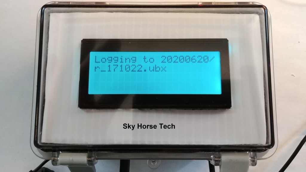
Here is what the front of our rover looks like with the SparkFun 20×4 serLCD display:
Here’s what the wiring inside of our IP67 rover module looks like:

Note that our rover module is setup as a land-based rover designed to be attached to a mobile survey pole. This could just as easily be implemented, without LCD display, in a UAV scenario where the F9P is logging data to the Feather M0 mid-flight. To take advantage of the full functionality of the Feather M0 in a UAV setup, it would be ideal to link the Waypoint/Timestamp switch (INTerrupt & GND) to your onboard camera’s shutter event. In Ardupilot, for example, you can push that connection high (5v) when the camera triggers an event such as commands DO_SET_SERVO or DO_SET_RELAY on your servo rail are pushed. This will allow for the merging of your raster (photos) and vector (timestamp on log file) for PPK missions.
Remember, this Feather M0 logger can be added to your rover OR base module. The default is Rover mode however if setting as a Base logger simply place a jumper wire between A0 and GND (see wiring diagram above).
One other item of note is the optional attached battery (~150mAh 3.7v LiPo) as seen in the picture above. This is connected to the Feather M0 board and is a backup source of power in case your main power drops for even a second. This backup battery provides power to the Feather M0 as well as the connected ZED-F9P module. Otherwise, as mentioned previously, if your main power source fails then the data you have logged in the current SD-card file will be lost forever. Bonus: The backup battery is automatically charged through the Feather M0 board by your main power source.
Okay, I have created a log file on my rover. Now what?
If you’ve followed along this far you’re probably familiar with processing the RAWX/GNSS data created by the ZED-F9P. Basically, you will take this rover .ubx file and process it in RTKLIB to create RINEX files (observation and navigation files) for PPK processing. Using these RINEX files in conjunction with data from a base observation file (from your own base module, a local CORS station or NTRIP caster) you can create a solution with centimeter grade accuracy.
Once you have removed the SD card from the Feather M0 logger you’ll place that in the SD card reader of your choice to see the files created. The file structure will look something like this below, with folders created with YYYYMMDD format used and individual files beginning with r_*:

If you open one of these files with a text editor you’ll see unreadable data, which are binary RAWX messages, mixed in with an occasional NMEA message ($GNGGA):

Next, we will select the file of our choice (one created during time frame you were running a mission for) and process using RTKLIB to create .obs and .nav files in RINEX format. For ZED-F9P PPK we will use RTKLIBExplorer’s version of RTKLIB as his version accounts for dual band as well as BeiDou satellites. The latest version (as of this post creation) is Demo5 b33c. He has excellent instructions for steps to take in post-processing. One of the first steps after collecting the GNSS data is to run RTKCONV.exe to take our RAWX binary file (.ubx) and convert it to RINEX files.
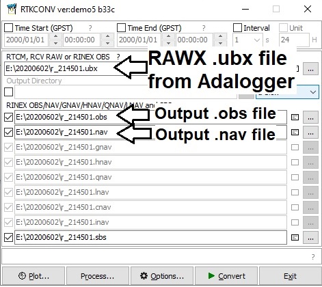
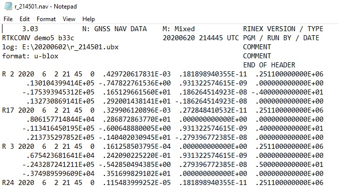
Here we enter our .ubx file from our rover’s logger and create the .obs and .nav files. Again, review RTKLIBExplorer’s multiple posts regarding this tool for full instructions.
Once we have Convert’ed this file we can then view our output .nav and .obs files to confirm the data appears to be reasonable.

Once we have these two files generated we are 2/3rds of the way home. Now we just need an observation file from a base station. If you have a ZED-F9P base module you would follow the same method for the base as we did for the rover above in generating RINEX file(s). Another option is to use RINEX files from a nearby (< 10-20km) CORS station. This is a free service in the U.S. and is available for each day of the year, 24/7. Find the CORS station near you, for us it is NJWC. In that station page, on the left side menu, select option ‘Custom Files (UFCORS)’. On the next page enter the day/time you would like the base data for (same time that rover log file was created), be sure to account for GMT (we are GMT – 4 hours). Finally, click on ‘Get CORS data file’ button at the bottom. This will allow us to download the zip file with the obs and nav files (obs file ends with *.o and nav file ends with *.n). With the 2 rover files and at least one of the base files we can then run RTKLIB’s RTKPOST.exe to create a PPK solution.
Materials list
SparkFun ZED-F9P SMA version*: https://amzn.to/3iFAc9p
*For non-SMA (older) version of F9P get U.fl to SMA connector: https://amzn.to/3hEOSVd
SparkFun Bluetooth module: https://amzn.to/3hDHiKj
Header kit for connecting wires to F9P: https://amzn.to/3iEK4R1
SparkFun 20×4 SerLCD – RGB Backlight (Qwiic): https://amzn.to/33Mc7cb
Qwiic Cable Kit: https://amzn.to/2SNfr0u
Adafruit SD card logger: https://amzn.to/3iPcJlD
Adafruit headers kit: https://amzn.to/3dilIKK
Waterproof case with mounting plate (size optional): https://amzn.to/2RM51xH
Waterproof wire connectors: https://amzn.to/32z2mNU
Waterproof USB connector: https://amzn.to/33DORLY
Momentary push buttons: https://amzn.to/2SNfx8m
Optional items:
Survey pole: https://amzn.to/3iJELjm
V-mount adapter: https://amzn.to/32zREGR
V-mount male clip: https://amzn.to/3c4qZFg
Pole clamps for Blind Spot and phone bracket (get 2): https://amzn.to/35HThnP
Blind Spot Power Junkie port: https://amzn.to/3c4s3sE
Batteries for Blind Spot (w/charger): https://amzn.to/3iEjkQr
Phone bracket with 1/4″ screw: https://amzn.to/3ktBBQT
Wire for rover and base: https://amzn.to/3iER1kO
Harxon higher end GPS500 or GPS1000 antenna (see Harxon website or eBay)
or use simple GNSS antenna for initial setup: https://amzn.to/3c6R5HV
Hopefully this will help you in setting up a SD-card logger on your rover and/or base ZED-F9P. Here is a supplemental video we created to show briefly what this looks like in operation:
Happy F9P’ing!
