
Update: Please see the complete Materials List at the bottom of this page with links to each of the items needed to build the base and rover.
In this article we discuss the uBlox ZED-F9P module and how we used those to obtain centimeter grade accuracy in an RTK GNSS system.
Here’s a video that we created which provides an overview of the process:
Why would we need an RTK rover and/or base in a UAS business? Simple, in order to obtain both relative and absolute accuracy we need to know where on Earth the drone actually is. From construction sites to inspecting high-power electric lines, RTK has a place in each workflow.
Swiss tech company uBlox has been making GNSS receivers for years, however with the ZED-F9P they entered the realm of multi-band GNSS. The difference between single-band and multi-band is a matter of accuracy measured in meters vs centimeters. The single-band accuracy can be resolved somewhat with post-processing using programs such as RTKLIB. With the ZED-F9P, the multi-band module performs that processing in the chip and errors such as integer ambiguity and ionospheric interference are resolved on the fly.
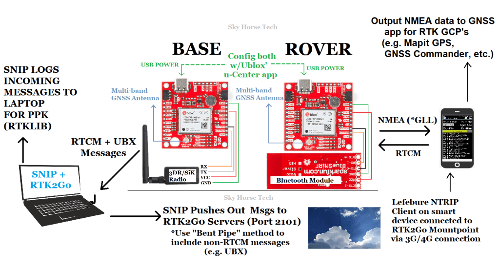
Here is what our total system looks like, from base to rover:
One of the great things about this F9P chip is the price, you can pick one up for around $225 which makes RTK a very affordable goal. In the video embedded above, we discuss the various companies that are offering the F9P module in their development boards (e.g. SparkFun, Drotek, Ardusimple, even uBlox themselves). We went with the SparkFun board, they have an online store with all of the accessories that you will need for this project. Other F9P tutorials that you’ll find online use other boards such as the uBlox C099 development board or an Ardusimple board. Two excellent resources for setting up F9P modules are rtklibexplorer and Roby aka Deep South Robotics. One thing to keep in mind is all of these boards have different manufacturers but they have one thing in common, the ‘brain’ which is the ZED-F9P chip. This means the way you program a SparkFun board is the same way you would configure a Drotek board. The wiring schematics and attachments to each board will differ but the code running behind the scenes is the same.
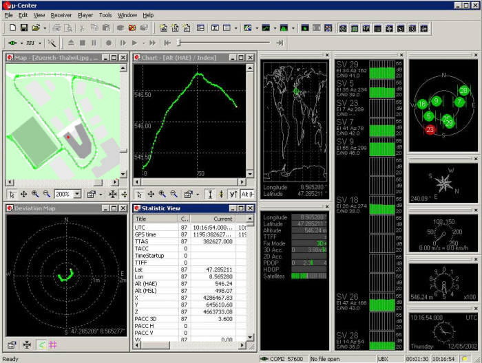
This brings us to how we configure these F9P boards. The simple answer is uBlox’ u-Center which is a free program built to configure all of uBlox’ GNSS boards. There are many YouTube videos on how to get this program running and talking to your F9P board, Google is your friend here. Basically, you will connect your F9P board to your computer via a USB cable, u-Center recognizes that COM port, connects to it and allows you to configure it through this channel. You can also connect via one of the UART ports but that is a bit more challenging.
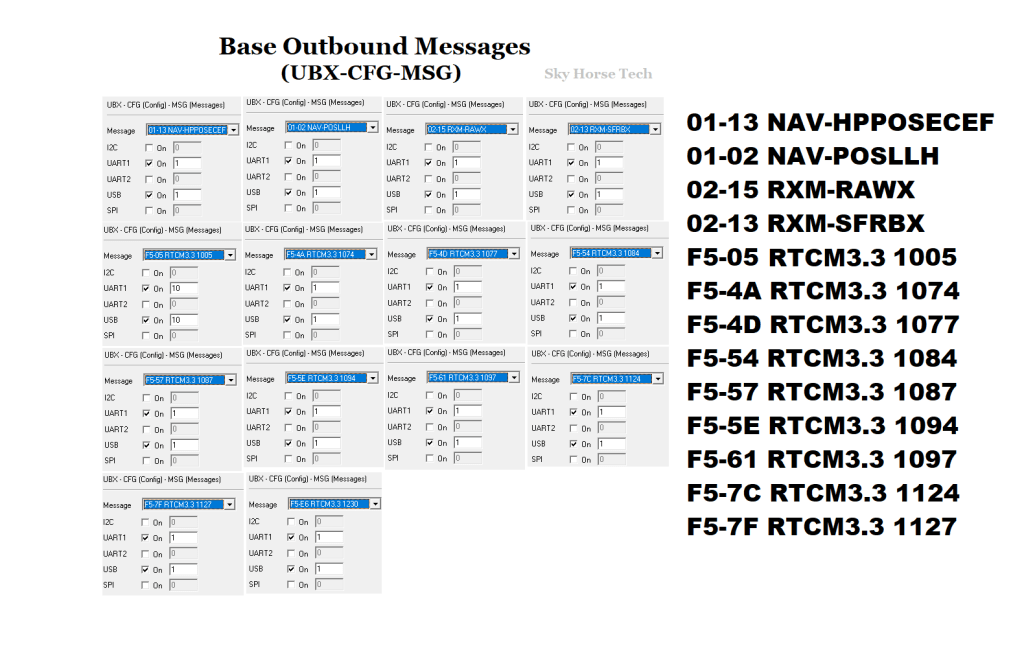
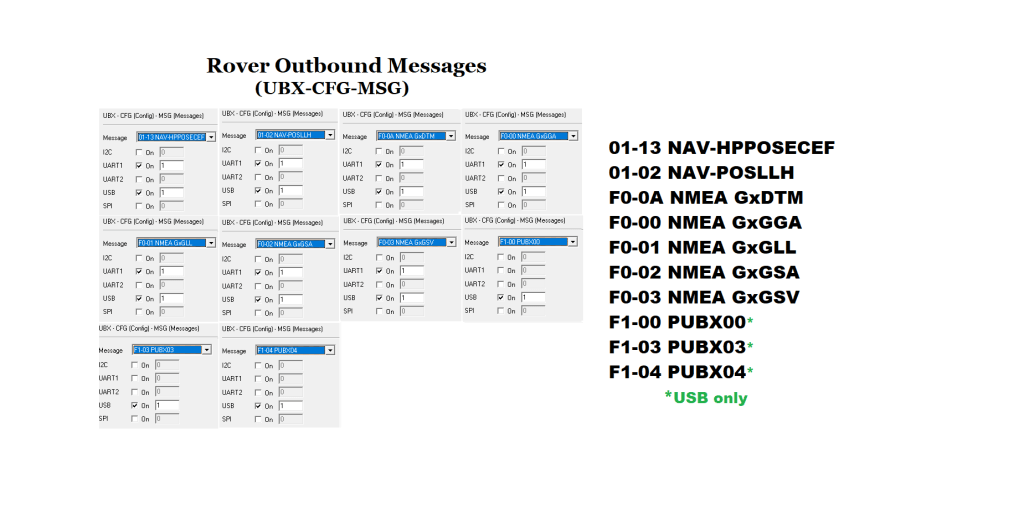
Watch our video embedded at the top of this article, it will shed additional light on how to use u-Center. One of the main settings you’ll want to update in your base and/or rover module are the messages that each module transmits (RTCM, UBX, NMEA, etc). Note that when you receive these F9P modules in the mail, they will always have a default configuration and need to be updated to fit your needs (base vs rover).
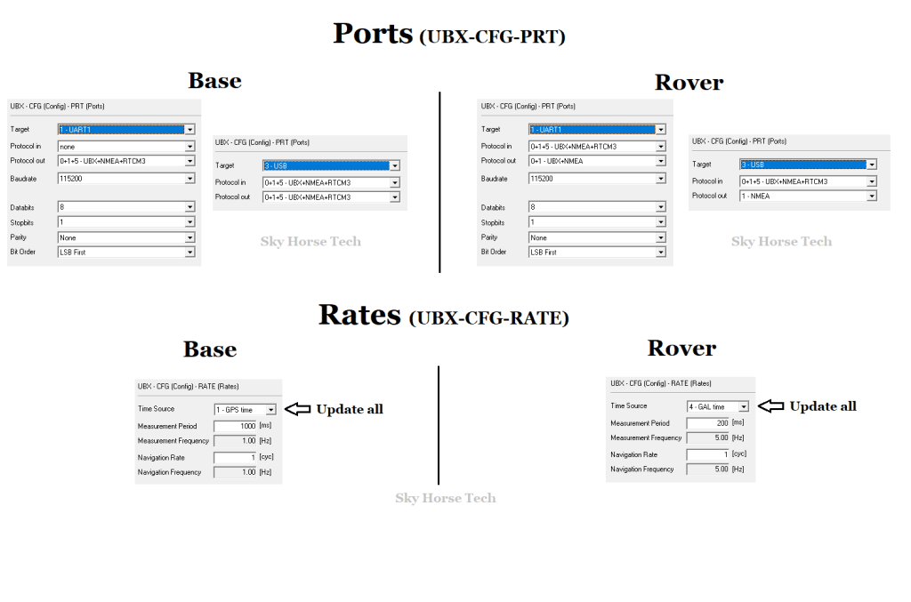
Here is a look at how we have our base and rover messages configured:
Another critical element that needs to be configured are the Ports and Rates settings:
The next critical part of this Base/Rover setup is to get your corrections messages from the Base to the Rover. There are many ways to accomplish this, it all depends on your needs. Will your base always be in the same static location? Will your rover be miles away from your base at some point? The answer to those types of questions will ultimately decide for you how your setup will look. For Sky Horse, since we know that we wanted our base to potentially be mobile and our rover may be miles away from the base at any point we added SiK/3DR radios along with an NTRIP caster to transmit those locations over a cellular network. Radios are used on the base module to send the corrections to our base laptop (remember we want the base to be mobile so laptop instead of desktop). The NTRIP caster is used to transmit corrections from our base laptop over the internet which can be picked up anywhere with a cellular or wi-fi signal.
We are using a standard SiK radio (915mHz) and configured those using Ardupilot’s Mission Planner. In our case we are using a baud rate of 115,200 across our system since the bluetooth module we are using on the rover uses this rate as a default. Again, Google and YouTube are chock full of videos showing how to use Mission Planner to config SiK radios so we won’t get in the weeds here with that discussion.
Another element in our lifecycle is the use of SNIP as an NTRIP caster. This is a free service (up to 3 ports free) and only takes an email to their support center to get your caster created and live with a mountpoint and username/password of your choice. Once you have your mountpoint registered with SNIP, you can download their free interface which will run on the base laptop. This will read in the corrections from your COM port (USB) and send them to a static IP. If you are like us and do not have a static IP, don’t fret, there is a solution. The nice people at SNIP have also created a free service called RTK2Go which acts as a static IP.
Here is how our SNIP interface appears on our base laptop:
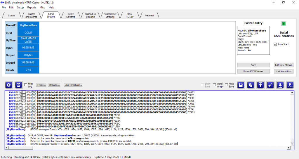
This is a look at our Serial Streams tab, you’ll see it is pointed to COM7 which is the USB port that our Sik radio is connected to (which is connected to our base ZED-F9P module). SkyHorseBase is what we named our Serial Stream mountpoint. In the log screen below that you will see the data that this port is reading in, including binary UBX messages and standard RTCM messages (these are the messages shown in the u-Center screenshot above). If data is flowing you will see the Input data rate increasing every second.
Next, in order to transmit those messages we are reading in from our COM/USB port, we need to send those to our RTK2Go mountpoint. Note: At this point, if you have a static IP that you can send to, you would use that instead of RTK2Go. To transmit those messages to RTK2Go we need to add that stream in the Pushed-Out Streams tab. Similar to setting up a SNIP user/password you would just need to send the RTK2Go support center an email with the mountpoint name that you would like to configure and use.
Here’s a look at our Pushed-Out Streams tab:
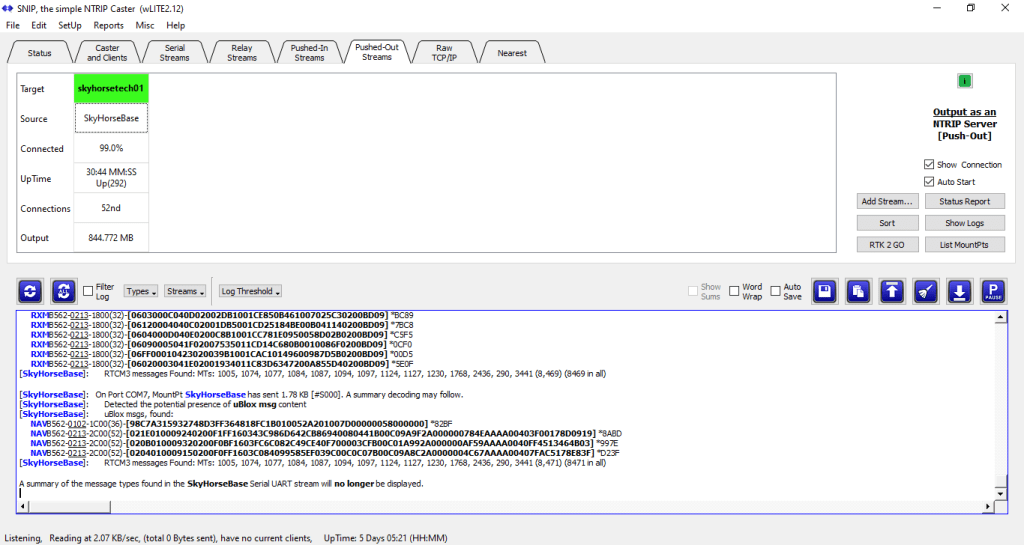
Here you can see we setup a RTK2Go mountpoint named ‘skyhorsetech01’ which is pulling data from our SNIP mountpoint named ‘SkyHorseBase’ (which was configured in the Serial Streams tab).
There are several other options available with this SNIP/RTK2Go model, including logging corrections data to your laptop, sending logs to an external FTP site, etc. For PPK processing we are using the file logging feature so that we have our raw data available for RTKLIB processing later on. This logged data would reflect our base data. Note that you can also read back data from your rover in the Pushed-In Streams tab but we are not using that method. Instead, we are logging the rover data on our smart device connected to the rover module.
Now that we are pushing out our corrections to a static URL (http://rtk2go.com:2101/) we can access our mountpoint there from anywhere.
This takes us over to the rover module where we will access those corrections and use them.
For our rover we have it setup with a bluetooth module connected by the UART1 port on the F9P module. SparkFun has additional info available in the GPS-RTK2 Hookup Guide with regard to adding a bluetooth module.
There are several free NTRIP client apps that can be used on your rover’s connected smart device, we are using the free app Lefebure NTRIP client. This will go out to our RTK2Go mountpoint, pull in those RTCM corrections and transmit them through bluetooth to our rover module.
Here’s what our settings look like in Lefebure NTRIP client:
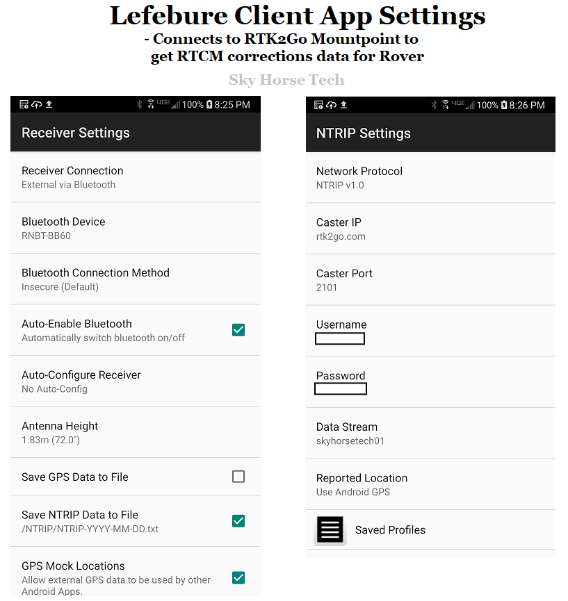
If you are using this rover to mark GCP’s or any type of control point through another app (e.g. MapItGPS, GNSS Commander, etc), you’ll want to turn on the GPS Mock Locations tab here. This will also require you to update your phone settings to allow this app to act as your actual GPS location instead of the phone’s not-so-accurate GPS location.
At this point, you have the basic components necessary to have your base generate GNSS corrections, transmit them via SiK radio to your base laptop, that laptop then reads in that data from your COM port and sends them to SNIP and RTK2Go. Your rover then picks up those corrections via Lefebure NTRIP client and sends them to the rover F9P module through bluetooth. The rover module then takes in those RTCM corrections, automatically processes them, sending out NMEA messages which, if you’ve configured everything correctly, will provide centimeter-grade accuracy.
One additional diagram which may be of some help are the wiring diagrams we have used for our base and rover modules:

If you have standard soldering skills you should be just fine hooking this up. Note that we soldered headers onto our boards instead of soldering the wires directly, this allowed us to update our wiring while testing, as necessary. Otherwise, if you solder the wires directly to the board there is a potential for headaches (de-soldering) if that wiring needs to change later.
As a wrap-up, we would just say if you have any interest in setting a F9P base and/or rover up and you have any sort of technical background or interest, you can do this. Google and YouTube have plenty of resources, although this multi-band module is fairly new the concept of RTCM corrections has been around for awhile now. This means there are plenty of older online articles out there which have been created for uBlox’ M8T or M8P modules but you can leverage those discussions as they may also relate to the underlying concepts behind the ZED-F9P module.
Good luck!
Materials List:
Rover module:
Survey pole: https://amzn.to/3iJELjm
V-mount adapter: https://amzn.to/32zREGR
V-mount male clip: https://amzn.to/3c4qZFg
Waterproof case with mounting plate (size optional): https://amzn.to/2RM51xH
Waterproof wire connectors: https://amzn.to/32z2mNU
Waterproof USB connector: https://amzn.to/33DORLY
Pole clamps for Blind Spot and phone bracket (get 2): https://amzn.to/35HThnP
Blind Spot Power Junkie port: https://amzn.to/3c4s3sE
Batteries for Blind Spot (w/charger): https://amzn.to/3iEjkQr
Phone bracket with 1/4″ screw: https://amzn.to/3ktBBQT
SparkFun ZED-F9P SMA version*: https://amzn.to/3iFAc9p
*For non-SMA (older) version of F9P get U.fl to SMA connector: https://amzn.to/3hEOSVd
SparkFun Bluetooth module: https://amzn.to/3hDHiKj
Header kit for connecting wires to F9P: https://amzn.to/3iEK4R1
Wire for rover and base: https://amzn.to/3iER1kO
Harxon higher end GPS500 or GPS1000 antenna (see Harxon website or eBay) or use simple GNSS antenna for initial setup: https://amzn.to/3c6R5HV
Base module:
915 mHz SiK radio set for base module: https://amzn.to/35KRNcG *One half goes on base module and other half on base laptop to receive data *Optional 3m USB extension: https://amzn.to/35FotnT to use on base laptop Sik Radio Antenna
SparkFun ZED-F9P SMA version*: https://amzn.to/3iFAc9p
*For non-SMA (older) version of F9P get U.fl to SMA connector: https://amzn.to/3hEOSVd
Waterproof case with mounting plate (size optional): https://amzn.to/2RM51xH
Waterproof wire connectors: https://amzn.to/32z2mNU
Waterproof USB connector: https://amzn.to/33DORLY
12V Solar Battery Box (2 watt): https://amzn.to/2RvBKXK
25 watt solar panel: https://amzn.to/3iIuJPi <- We upgraded the box above to use the 25w panel
12V DC connectors: https://amzn.to/3kqbJ8A
12V DC to 5V DC adapter: https://amzn.to/2ZJO2QC
TNC Male to SMA Female connector: https://amzn.to/32DWlzi *If using Harxon antenna on base
Harxon higher end GPS500 or GPS1000 antenna (see Harxon website or eBay) or use simple GNSS antenna for initial setup: https://amzn.to/3c6R5HV
Depending on your base antenna setup you may need SMA extension wire: https://amzn.to/3c479tX *Be aware of which type of connector you are extending (male vs female) as you’ll want the opposite of what it is being attached to
Update (5/31/2020): Watch our latest video showing how to setup a base station in a permanent location:

Well this project is very interesting.
You can also refer to using ESPrtk (ESP32) as an RTK profile for your project without U-Center.
ESPrtk supports WIFI and Bluetooth, LoRa, Ethernet and GSM 4G.
If you have time, feel free to contact us, we would like to give you 3 ESPrtk device activation key files (free) if you want to experience it.
Here’s the email for you: contact@esprtk.com.
Or you can go to http: esprtk.com.
(I also posted a similar comment on your youtube channel,).
LikeLike