Purpose: This piece of equipment will monitor water quality and automatically push the data through a 4G cellular link to a web dashboard in real-time.
Here at Sky Horse Tech we’ve recently taken an exciting path to integrate Unmanned Surface Vehicles (USV), designed to navigate waterways, into our fleet. There are existing, expensive USV systems that are available on the market today, however we chose to go the DIY route from the outset. After working with several environmental groups here in New Jersey, including stream cleanup groups and NJ Clean Communities Council, we noticed from the beginning the need for additional data around water quality in the local waterways. From our perspective, the USV was a natural fit to obtain that data.
Just having a USV navigating local waterways isn’t enough, we obviously needed onboard water quality sensors to collect that data and report it. Fast-forward to today and our system includes two ways to collect water data: 1) the use of Sensors and Probes (SaP) to collect water quality data along a waterway and geo-tag it for later analysis and 2) a system to collect actual water samples that can be sent to a lab for testing. We are 70% completed on the latter system and 100% complete on the former. With that in mind, we will show you some of the components of our SaP system and maybe that can help you or your organization in building something similar.
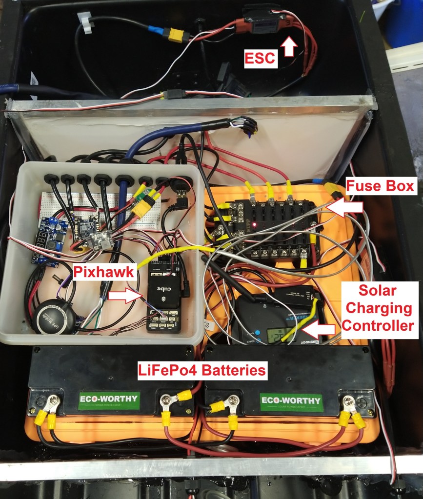
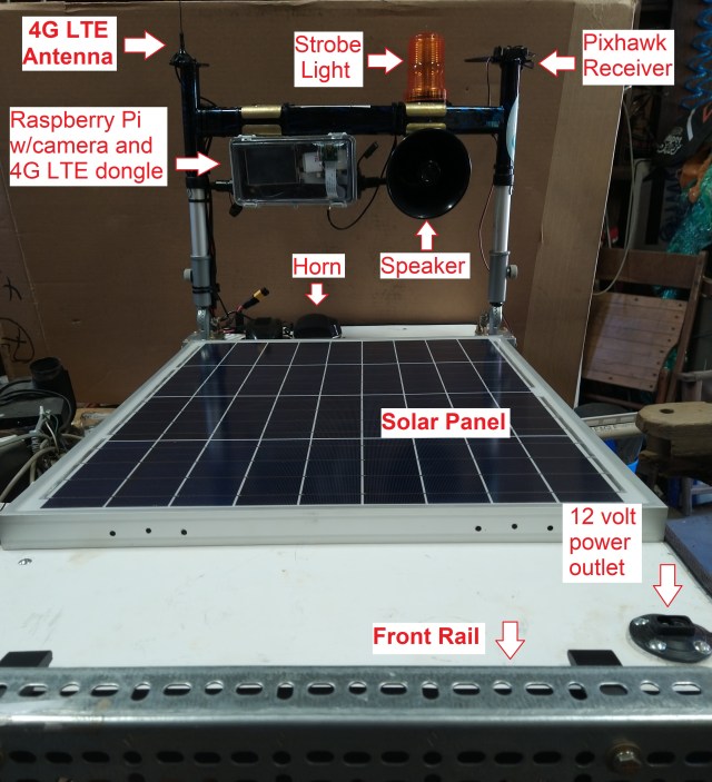
In future articles we will review additional systems on our autonomous USV including the use of a Pixhawk autopilot, ESC’s, waterproof hull, Raspberry Pi and camera, UAV Cast 4G/LTE software, horn, solar panel to charge the LiFePo4 batteries and more. Remember, this system has been built to be autonomous, where we will launch it at one point upstream and collect it miles downstream. All the while, we will be monitoring the video feed, sensor and probe (SaP) data, GPS coordinates, battery capacity, etc. in real time. We will also have the ability to switch over to manual control in the places where it is warranted.
Probes and Sensors
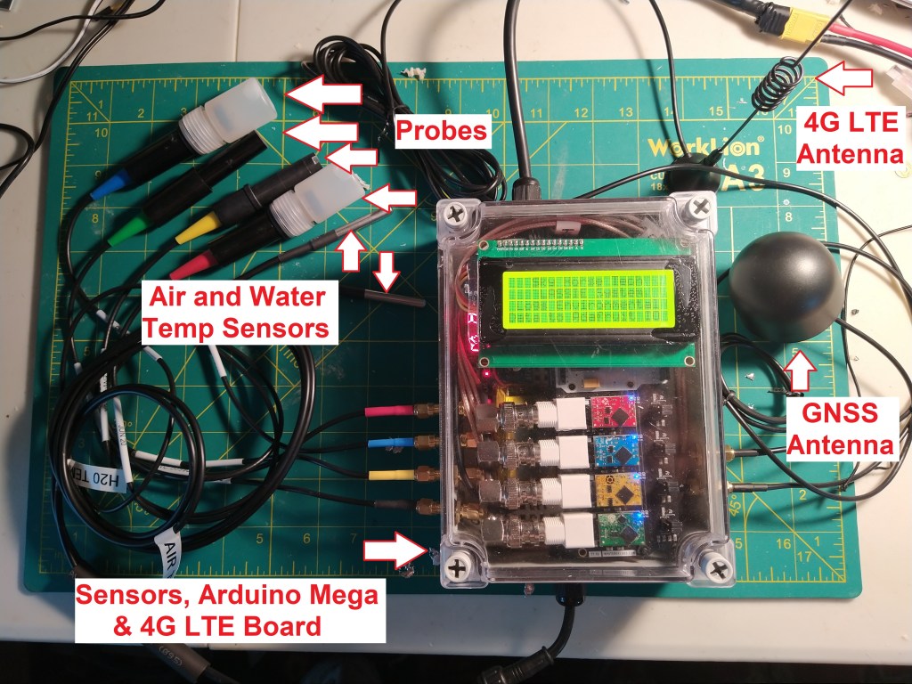
In this article we will focus on a single component of our onboard system, the SaP system in which we have 4 sensors and 4 probes housed in a waterproof case, sending live data to an Adafruit.io dashboard. Through that online portal we log each of the water quality data points. These logs are available for later viewing and analysis. Since each data point is geo-tagged we can export those into a post-production program such as ArcGIS Pro for visual presentation and discussion with stakeholders.
Overall our SaP system has three main components: (1) an Arduino Mega which is the brains of the operation, (2) Atlas Scientific sensors and probes which collect the data and (3) a 4G/LTE shield to transmit the data over a cellular network.
In the initial analysis phase we researched several types of water quality sensors and found that one of the best (if not THE best) systems are designed, built and sold by Atlas Scientific out of Long Island City, New York. Their probes and sensors are used around the world for detecting and reporting such data in projects ranging from aquariums to industrial applications.
After researching the types of water quality data that environmental groups (e.g. EPA, DEP, USGS) use on a regular basis we decided to go with four common sensor types: pH, Dissolved Oxygen (DO), Oxidation-Reduction Potential (ORP) and Electrical Conductivity (EC).
Additional information from the U.S. Geological Survey website:
pH
Dissolved Oxygen
Oxidation-Reduction Potential
Electrical Conductivity
When building an integrated system such as this it’s important to have electrical isolation between the sensors so that electrical noise from other nearby components do not cause interference. Atlas Scientific offers individual voltage isolator boards but they also recommend the Whitebox Labs Tentacle Shield where you can plug in up to four Atlas Scientific EZO sensors and the Tentacle shield isolates each of those sensors completely. It makes for a nicer, more compact build in our case. We bought our Tentacle shield around 6 months ago and when we went back to document this we noticed that initial shield is now retired and they have released (as of June 2021) updated versions. Now they have one new shield for Arduino and one for Raspberry Pi. You’ll notice that the Arduino shield has a larger footprint of the two and the RaPi uses the standard GPIO pins.
The necessary power for the Tentacle shield is supplied through the Arduino Mega and 4G/LTE shield. For the four probe output connectors, they use a BNC type connection. We went with a 90-degree BNC male to SMA male wire like this. From there we go to an SMA connector (female-to-female) like this that goes through the side of the box. Finally, from the female SMA on the outside of the box, your probes with SMA wires will connect directly there. In total, our box uses 6 of these connectors: 4 for the probes, 1 for the LTE antenna and 1 for the GPS antenna.
Atlas Scientific sensors and probes
Full disclosure: These links are through the Amazon Affiliates program. We will receive a small credit if you purchase an item through our links. All of that money will go back into future projects such as this:
Atlas Scientific EZO pH Sensor: https://amzn.to/3vrQfhw
Atlas Scientific EZO EC Sensor: https://amzn.to/3p1rzKA
Atlas Scientific EZO DO Sensor: https://amzn.to/3wDDrFg
Atlas Scientific EZO ORP Sensor: https://amzn.to/3vpGYH1
Atlas Scientific mini pH Probe: https://amzn.to/2QVBDIp
Atlas Scientific mini EC Probe: https://amzn.to/3fqQAvz
Atlas Scientific mini DO Probe: https://amzn.to/3flYplY
Atlas Scientific mini ORP Probe:https://amzn.to/3vkJuOB
Atlas Scientific Calibration solution: https://amzn.to/3wys1lW
Atlas Scientific EZO Single Electric Isolator: https://amzn.to/34j471B
Atlas Scientific USB to Serial Converter: https://amzn.to/3i0zFBx
Atlas Scientific Inline Voltage Isolator: https://amzn.to/3flYG8u
Be sure to check out the Atlas Scientific datasheets for each EZO sensor as they have a busload of information for the related sensor. The datasheets are located under the Documents and Downloads section of each sensor’s page:
Atlas Scientific pH EZO Sensor Info
Atlas Scientific DO EZO Sensor Info
Atlas Scientific EC EZO Sensor Info
Atlas Scientific ORP EZO Sensor Info
Temperature Compensation
In the Atlas Scientific website under each specific datasheet there are detailed instructions on how to calibrate them. We also found this video by Reck’s Design and Fabrication to be helpful in setting up and calibrating Atlas Scientific sensors using the Whitebox Lab’s Tentacle Shield and Arduino IDE. In 3 out of 4 of those sensors (ORP excluded) they also have the ability to perform temperature compensation, which will include your water temperature sensor’s output to account for very cold or warm temps and adjust the sensor reading algorithmically. In order to obtain those temp readings we use DA18B20 sensors which are ‘one wire’ sensors. This means you can have multiple sensors connected to one pin on your Arduino Mega. We use one for air temp and one for the water temp, the latter being most important for sensor temp compensation. We run this wire (yellow) to pin 39 on our Mega along with 5v (red) and ground (black). Here is a great tutorial on setting up those DA18B20 sensors, including how to detect their hex address if using more than one at a time: https://lastminuteengineers.com/multiple-ds18b20-arduino-tutorial/
For example, in our sketch we first read in the sensor data from both air and water:
airTempC = sensors.getTempC(airSensor);
h2oTempC = sensors.getTempC(h2oSensor);
Then we send that water temperature reading to the sensor for automatic compensation:
if (h2oTempC > 0) {
  send_cmd_with_temp("T,",h2oTempC,3,99);  //command, temp var, var length, ezo address #
 }
See the Atlas Scientific GitHub page with examples of Temp Compensation and Reading Temp sketches. The send_cmd_with_temp() function below is leveraged from the Atlas Scientific sketch where they use a universal send_cmd_with_num() function throughout. Their function is declared in their EZO_i2c.h library. Here is how we have used that for our purposes to read the temp sent as a parameter into the function and then writes it to the EZO board address id that is also sent as a parameter.
void send_cmd_with_temp(const char* cmd, float num, uint8_t decimal_amount, uint8_t addr){
  String temp = String(cmd )+ String(num, decimal_amount);
  const char* pointer = temp.c_str();
    Wire.beginTransmission(addr);
    Wire.write(pointer);
    Wire.endTransmission();
    Serial.print(" ********  TEMP COMPENSATION SENT: ");
    Serial.print(pointer);
    Serial.println("   ********");
}
Adafruit IoT/MQTT Dashboard
As for monitoring this probe and sensor data in real-time, we have always loved Adafruit as a supplier and also as an innovator so it was a natural decision to use Adafruit.io for their IoT/MQTT dashboard. Adafruit has a free version that you can definitely take advantage of, however since we were sending so much data we went ahead and upgraded to the Adafruit IO+ subscription which gives us loads of data at a higher frequency (data points/minute).

4G/LTE Shield
Now that we are capturing the data and have a place to store it, we need a way to transmit that data to the cloud. One straightforward way is through a 4G/LTE cellular shield which we use to upload the sensor data to the Adafruit dashboard. We ended up going with a SIM7000 shield offered by Botletics. Timothy Woo at Botletics designed this board, had it built and was kind enough to document Arduino code examples and libraries needed to support it. The MQTT code he included is built off of the Adafruit FONA library, with a slight change to accommodate the SIM7000 needs. We strongly recommend you to use the Botletics IoT_Examples.ino sketch as your starting point and add code as needed (logic for Adafruit.io, Atlas Scientific sensors, etc) Note: We include links below for additional information on all of the items we discuss here.
One important thing to know is that when uploading and using the Botletics sketch is the need to use the Botletics custom Adafruit FONA library. We found that it was simple to download and get working, however if you ever update or import an Adafruit library after that which also uses the Adafruit FONA library you will probably need to overwrite that (again) with the Botletics custom FONA library. We found this out the hard way, after we had the SIM7000 uploading data to Adafruit regularly, it stopped working suddenly. We realized that we had added an Adafruit library in a completely different project which overwrote the custom Botletics FONA library so we needed to revert back. One sure sign is you’ll see through your serial monitor that it is attempting to connect to Adafruit.io but is being rejected on their side with an MQTT subscription error. One other strange quirk we found is that occasionally you may have an MQTT connection issue out of nowhere. By uncommenting the #define MQTT_DEBUG line in the Adafruit_MQTT.h library under /libraries/Adafruit_MQTT_library/ this seems to resolve various issues. Some suggest to simply leave that debug line uncommented when encountering stability issues, it will use up a bit more memory if uncommented. See this article by Katrina Siegfried for helpful debugging hints in Adafruit FONA.
Note that there are other 4G/LTE shields that can be used for projects such as this, including the SparkFun shield which is similar. Check out that SparkFun page as they have very helpful information regarding LTE and IoT with these shields. Much of the information that is applicable to one LTE shield is universal to all, some aspects may strictly be for that board however. Shop around and see which LTE board is best for your use case.
SIM Card
Whichever LTE shield you end up using, you’ll need an LTE Cat M1/NB-IoT SIM card for it to communicate. Note that these SIM cards are not your standard SIM cards but are created specifically for lower data transmission rates for IoT (no calling/talking). We went with Hologram for our SIM cards as well as our carrier as their data rates are pretty reasonable. In our USV’s separate onboard autonomous navigation system it also communicates over an LTE connection. However, that data stream also sends video (480p) so the data bandwidth is much higher. In that case, after racking up considerable fees using standard IoT data plans, we switched that SIM card over to a Hologram high volume plan which in the long run is much easier on the wallet. However, this particular SaP sensor system uses minimal bandwidth so you can stick with an IoT cellular plan (pay as you go, ~0.40c/MB).
Build on Top of the Arduino Foundation
All of this is dependent on the Arduino Mega which is running the sketch to read the sensors, send MQTT data, get GPS and cellular signals, etc. It’s possible to use a smaller board such as the Uno but you will run out of memory quickly if using all of the components that we have used. Don’t mess around, just go with a Mega.
As you can see in the Adafruit.io screenshot above, from any place on Earth we are able to view water quality data in real-time, as it is collected on a local waterway. Since the data points are geo-tagged we can also see where the USV is currently located. This Adafruit.io dashboard is easily customizable, we went with the dial format for ease of reading but there are other charts or viewing schemes that can be used instead.
Eventually, we’ll be using this logged, geo-tagged data stored on the Adafruit.io site and exporting that into ArcGIS for visual referencing of water quality data on a river or waterway.
Build the Sensor Sandwich
In short, we have three main boards (Arduino Mega, SIM7000, Whitebox Labs Tentacle) in a tasty sensor sandwich.

LCD Screen
In your lab, office or living room you can set this up and test it completely using the Arduino IDE Serial Monitor. However, when using this out in the field you probably won’t have that capability. In the absence of a serial monitor or laptop we’ll need to use an LCD screen to give visual confirmation of what is happening. We went with a 20×4 LCD screen with a green/yellow backlight which we have used in numerous projects before. Note: We attempted to use an OLED screen initially, however these use up much more memory and can cause buffering issues. In your Arduino sketch, wherever you want to write out to the LCD screen just add a snippet to do that: 1) clear the screen, 2) place the cursor, 3) write:
lcd.clear();
lcd.setCursor(3,0);
lcd.print(F("Sky Horse Tech"));
lcd.setCursor(4,1);
lcd.print(F("LASSIE System"));
lcd.setCursor(1,2);
lcd.print(F("Logs Environmental"));
lcd.setCursor(0,3);
lcd.print(F("Data to Adafruit IO"));
delay(2000);
Here is an instructable for setting up and using an LCD screen with Arduino.
Powering Up
For our system we are using a DC buck converter that takes an input voltage range of 4-40 volts DC and the output voltage is adjustable from 1.25 to 37v DC at 2 amps. This allows you to use a range of LiPo batteries as input via XT60 connectors (or any DC connector) and you have a steady, reliable output voltage to your Arduino. We have ours set to output 8 volts which Arduino is happy with. On the input side we have two 16ga wires (+/-) connected to an XT60. On the output side we use a right angle barrel jack (5.5 x 2.1mm) that fits nicely into the Arduino directly. Remember, we are also using the 2800mAh LiPo connected to the Botletics SIM7000 LTE shield which is charged by this incoming voltage via the Arduino.

Ok, we’ve gone over the main components and hopefully this has given you a better sense of what is needed to build it. Just to make things a bit clearer, we’ve compiled a checklist below to navigate you through the project.
DIY Build Checklist
- Solder headers onto SIM7000 if not already attached
- Solder antenna jumper on SIM7000 if using active GNSS antenna (See Botletics wiki)
- Make backup copy of Adafruit_FONA library if already exists in your IDE (optional)
- Add Botletics Arduino code/libraries w/custom FONA in Arduino IDE (Use the IoT_Example.ino as a starting point and build off of that, also see Botletics IDE page for importing libraries)
- Activate SIM card (e.g. IoT plan on Hologram.io)
- Insert SIM card in SIM7000
- Attach SIM7000 shield on top of Arduino Mega (See instructables details)
- Attach LTE and GPS antennas to SIM7000 (either default passive or your active antenna)
- Attach up to 4 sensors on Tentacle Shield
- Attach Tentacle Shield to SIM7000/Mega stack
- Attach Probes to Tentacle Shield (BNC->SMA connectors)
- Attach LCD screen I2C wires (SDA/SCL) and +/- to Tentacle (optional)
- Create Adafruit.io account and obtain username with unique key
- Update Arduino sketch with Adafruit.io username and key. If you use the Botletics IoT_Example.ino sketch as your basis as we did you’ll see the entry for #define AIO_USERNAME and AIO_KEY around line 118)
- Update Arduino sketch with SIM info (e.g. APN, username, PIN, etc). If using IoT_Example.ino you’ll see these settings around line 225: fona.setNetworkSettings(F(“hologram”)) if you are using Hologram as your SIM carrier, they don’t require username/password. Other carriers may require that and you’ll see an example commented out in the same area of the sketch: fona.setNetworkSettings(F(“your APN”), F(“your username”), F(“your password”));
- Add LCD code in Arduino sketch to display current status (optional). See example here.
- Add Atlas Scientific Arduino code to the existing SIM7000 Arduino code to read in sensor data and upload to Adafruit.io (See i2c_lib_examples and Arduino Mega example in Atlas Scientific GitHub page)
- Build dashboard and add sensor feeds on Adafruit.io (Plenty of examples at Adafruit; addt’l resources here and here). Note your feed names are case sensitive in Arduino sketch
- Upload sketch to Mega. Test, debug and update as needed
- Use Arduino IDE Serial Monitor and Adafruit.io to confirm expected results
- Drill holes for SMA, switch and wire gland holes as needed in waterproof box
- Add waterproof switch to positive wire of battery wires (optional)
- Connect LiPo battery (>1000mAh) to SIM7000 (double check +/- on battery connection)
- Add Mega/SIM7000/Tentacle sensor sandwich stack to waterproof box
- Add buck converter and adjust to 8v output
- Connect battery, GPS and LTE antennas and probe wires inside box
- Unit test with all components in box
Additional Resources
Hopefully you are able to use these links and examples as a starting point in your project. From our experience and research there are many, many ways to integrate all three of these main components (Arduino/SIM7000/Sensors). The only limit is your imagination. We definitely recommend using the Botletics IoT_Example.ino as your starting point with the Arduino side. When adding code that you aren’t familiar with, make small changes and test incrementally. Once that update works, add the next code segments as needed. Rinse, repeat.
Here are some additional links for purchasing some of the items listed above. Just noting again -> Full disclosure: These links are through the Amazon Affiliates program. We will receive a small credit if you purchase an item through our links. All of that money will go back into future projects such as this:
Botletics SIM7000 Shield: https://amzn.to/3wA2hFR
Waterproof box (7″x5″x3″): https://amzn.to/34k3cho
SMA through-box connectors: https://amzn.to/2SwGCiW
Temp sensors: https://amzn.to/3fvcYDN
Waterproof gland connectors: https://amzn.to/3vpfAc8
XT60 connectors: https://amzn.to/3fmYB4s
LCD screen (20×4): https://amzn.to/2Sxl9GV
Arduino Mega: https://amzn.to/34m0Qio
Lipo 2800mAh battery: https://amzn.to/34iFXod
Waterproof toggle switch: https://amzn.to/3i3mL5E
12v Buck Converter w/Display: https://amzn.to/3bZlI38
uFl to SMA connector: https://amzn.to/3fV3jFO
Right angle barrel jack wire: https://amzn.to/3c4cQJz
SMA extensions: https://amzn.to/3fsdFOm
BNC pigtail to SMA: https://amzn.to/3yLMm9l
4G LTE antenna: https://amzn.to/2TrU2NV
Active GPS antenna: https://amzn.to/3wK332X
Atlas Scientific EZO pH Sensor: https://amzn.to/3vrQfhw
Atlas Scientific EZO EC Sensor: https://amzn.to/3p1rzKA
Atlas Scientific EZO DO Sensor: https://amzn.to/3wDDrFg
Atlas Scientific EZO ORP Sensor: https://amzn.to/3vpGYH1
Atlas Scientific mini pH Probe: https://amzn.to/2QVBDIp
Atlas Scientific mini EC Probe: https://amzn.to/3fqQAvz
Atlas Scientific mini DO Probe: https://amzn.to/3flYplY
Atlas Scientific mini ORP Probe: https://amzn.to/3vkJuOB
Atlas Scientific Calibration solution: https://amzn.to/3wys1lW
Atlas Scientific EZO Single Electric Isolator: https://amzn.to/34j471B
Atlas Scientific USB to Serial Converter: https://amzn.to/3i0zFBx
Atlas Scientific Inline Voltage Isolator: https://amzn.to/3flYG8u
Stay tuned for future articles and videos regarding this USV project.
