
In this project we explore how to add RTK functionality to your UAS (drone), specifically a UAS using Pixhawk. In previous posts and videos we built a ZED-F9P base and rover for ground-based RTK projects, we will use the same F9P GNSS module here. Since we are adding this to a UAS we will need to miniaturize the footprint so we have the lowest possible weight onboard.
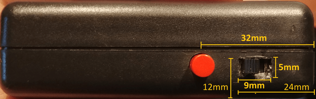
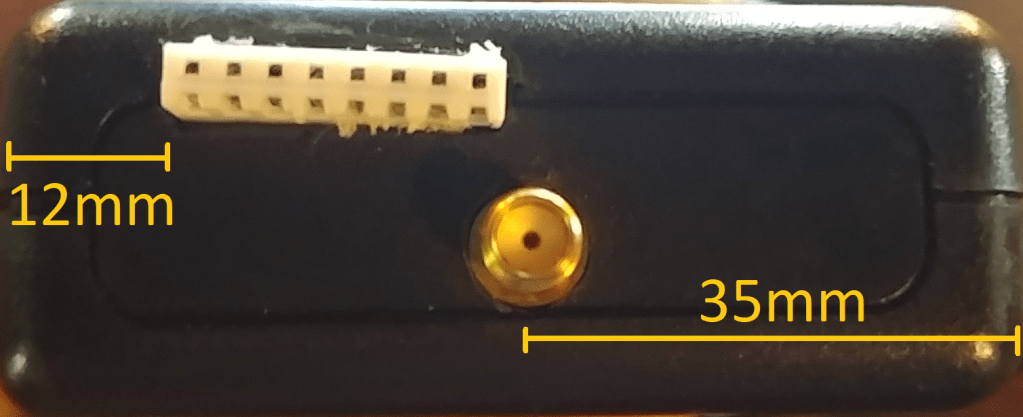
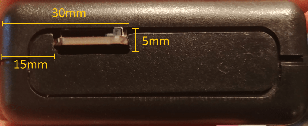
For the plastic outer shell we are using a standard project case and have made the necessary cutouts using a rotary cutting tool (Dremel) and drilled for holes. In the pictures below, we provide the measurements and placement of those cutouts. We also have a complete materials list at the bottom of this post for all of the components used overall.
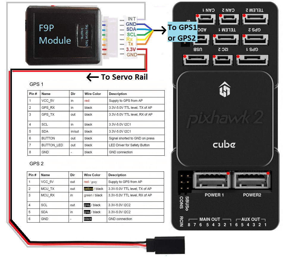
As with our previous ZED-F9P projects, we are pulling our base GNSS corrections into our UART2 port and also logging those coordinates to an Adafruit SD card logger. Luckily, the Pixhawk/Ardupilot software allows us to inject the GNSS corrections from our base (either with base connected directly to laptop or through SNIP/CORS/NTRIP). We inject those corrections to our GPS2 port on the Pixhawk which is also wired to the Tx/Rx (transmit/receive) ports on our F9P module (see wiring diagram below).
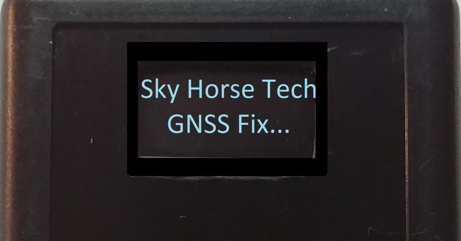
See our previous posts (and videos) How to Build an RTK Base and Rover and How to Add an Adafruit Logger with LCD Display for background on the complete system, this updated module would perform the same operations as the larger models but would obviously be easier to transport and is now communicating with Pixhawk. In that second link for the Adafruit Logger version, we discuss how to update the Arduino code on that logger with our custom code for adding on an LCD display (with links to our GitHub page). Similarly here, we created custom Arduino code for using an OLED display and posted that on a separate GitHub repository: SkyHorseTech/F9P_RAWX_Logger_OLED . As discussed in the prior post, the RTCM and UBX messages that are used by the logger and linked F9P can be customized to your needs. Please reference that for additional background on those settings.
Our module has an SD card logger but is not necessary for the use-case of our UAS since Ardupilot internally logs the GNSS coordinates on the Pixhawk if we program it accordingly, including geo-tagged/time-stamped photos taken by the UAS. The SD card logger simply provides us with a backup logging system and is available for non-UAS operations. Bonus: This smaller module can also act as a rover module for land based operations just as we have shown in prior articles. The only update needed would be to build a separate wiring harness (with male header) with connections to the 5v, GND, Tx and Rx wires on a 3DR/SiK radio and/or laptop. The UAS wiring harness (F9P->Pixhawk) and separate ground-based wiring harness (F9P->3DR Radio) could be swapped out within seconds, depending on the mission at hand. We have a complete wiring diagram below which outlines all of the necessary connections.
First, let’s go over how our module appears and the related cutout measurements. The box itself is rather small (3.54 x 2.76 x 1.10 inch) but packs a bunch of components inside:

Let’s take a look at the components inside of the module:
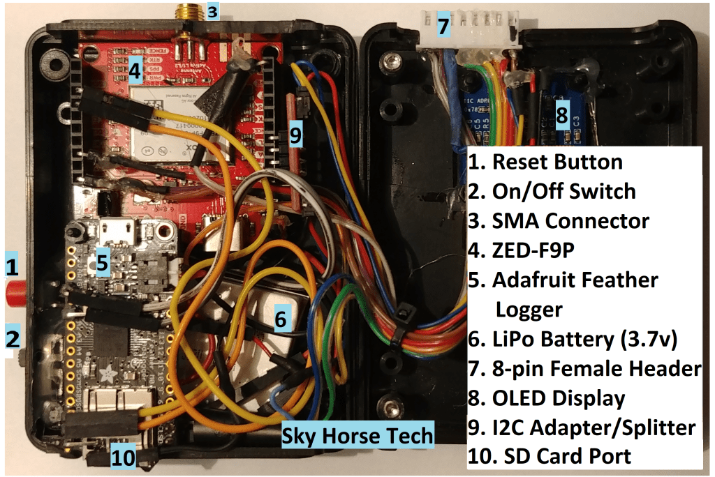
The 3.7v LiPo battery is connected to the On/Off switch so this can be powered externally (by wire) or internally (by battery) depending on the length of the mission. The Reset Button would reboot the system in cases where an error was encountered on startup. Notice the standoff screw between the F9P and the SD Card Logger. This keeps both units in place within the case. We hot glued the F9P to the case also which aids stability.
Wiring Diagrams


Settings in Mission Planner
See our original post and linked video How to Build an RTK Base and Rover to see how we inject GPS corrections into Mission Planner. Another step needed is to have our onboard F9P module use those corrections and use this as a secondary (or primary) GPS module for our UAS. See the Ardupilot link below with regard to GPS blending which is a guide on adding additional GPS systems such as this. Here are various documents on integrating GNSS modules with Pixhawk:
https://ardupilot.org/copter/docs/common-gps-blending.html
https://ardupilot.org/copter/docs/common-here-plus-gps.html
https://docs.px4.io/master/en/gps_compass/rtk_gps.html
https://discuss.ardupilot.org/t/ublox-zed-f9p-l1-l2-gnss-unit/31511/83
https://discuss.ardupilot.org/t/solved-zed-f9p-simplertk2b-pixhawk-2-1/52907/4
ArduPilot page on setting up RTK w/Mission Planner: https://ardupilot.org/copter/docs/common-here-plus-gps.html
Different GNSS systems, same theory:
Emlid: https://docs.emlid.com/reach/ardupilot-integration/
Swiftnav/Piksi: https://docs.swiftnav.com/wiki/Integrating_Piksi_with_the_Pixhawk_platform
ArduSimple’s F9P: https://www.ardusimple.com/simplertk2b-hookup-guide/
Sky Horse Arduino Github Repository for this project: https://github.com/SkyHorseTech/F9P_RAWX_Logger_OLED
Materials List
Full disclosure: We are part of the Amazon Affiliates program and will receive a small portion of sales if you purchase through links below. We place all residuals directly back into future projects.
SparkFun ZED-F9P SMA version*: https://amzn.to/3iFAc9p
*For non-SMA (older) version of F9P get U.fl to SMA connector: https://amzn.to/3hEOSVd
Adafruit SD card logger: https://www.adafruit.com/product/2796
Adafruit headers kit: https://www.adafruit.com/product/2886
Lithium Ion Polymer Battery – 3.7v 350mAh: https://www.adafruit.com/product/2750
Helical RTK GNSS antenna: https://www.aliexpress.com/item/4000685304133.html
Zulkit Project Boxes 3.54 x 2.76 x 1.10 inch (90 x 70 x 28 mm): https://amzn.to/3iJIMDu
Header kit for connecting wires to F9P: https://amzn.to/3iEK4R1
SparkFun Qwiic Adapter: https://amzn.to/33MoEwf
OLED Display 0.96 Inch SSD1306 I2C: https://amzn.to/2SIvsEK
Qwiic Cable Kit: https://amzn.to/2SNfr0u
Rainbow ribbon (10′): https://amzn.to/33NzSAr
8-pin male and female headers: https://amzn.to/33NliZO
On/Off 5mm slide switch: https://amzn.to/3ltB0zo
Reset push button 6x6x9mm: https://amzn.to/34OulZW
Standoff kit (used between logger and F9P): https://amzn.to/2FpMPas
Link to the Adafruit page with additional technical details on their SD Card adalogger: https://learn.adafruit.com/adafruit-feather-m0-adalogger
Link to the SparkFun F9P Hookup Guide: https://learn.sparkfun.com/tutorials/gps-rtk2-hookup-guide This page and the SparkFun website have tons of info on setting up the F9P.
Future enhancements within this system:
- Eventually we’ll be adding a gimbal with Sony a6000 mirrorless camera shutter triggered by Pixhawk/Mission Planner and geo-tagged photos logged with RTK coordinates. See: https://ardupilot.org/copter/docs/common-pixhawk-camera-trigger-setup.html and https://ardupilot.org/copter/docs/common-geotagging-images-with-mission-planner.html
Thank you for reading and good luck to anyone building their own!

WOW . Amazing project for RTK app.
Good work my friend. Keep working.
LikeLike